In today’s fiber optic network infrastructure, the fiber splitter is a very important component. It’s used in FTTH systems, PON systems, CATV systems, data centers, and corporate networks. Using the splitter effectively allows a single fiber to serve several users without the need for additional fibers, making the network more efficient and reducing the total costs.
What Is a Fiber Splitter?
A fiber splitter, also known as an optical splitter or optical power splitter, is a passive optical device that operates without any external power supply. Its primary function is to divide one input optical signal into multiple output signals based on a predefined split ratio or number of ports.
In a Passive Optical Network (PON) architecture, the fiber splitter is typically installed between the central office and end users, distributes optical signals from the OLT to multiple ONUs. Because fiber splitters contain no active electronic components, they offer high reliability, long service life, and low maintenance costs, making them a key element in “one fiber to multiple users” network designs.
Common Types of Fiber Splitter
Based on manufacturing technology, operating principles, and practical application requirements, several types of fiber splitter are available on the market. Each type differs in splitting capacity, structure, and deployment method, making them suitable for different network scales and environments.
1. FBT Fiber Splitter (Fused Biconical Taper)
FBT (Fused Biconical Taper) fiber splitter is one of the earliest optical splitting technologies used in fiber optic communication systems. With mature manufacturing processes and a straightforward operating principle, it is still used in certain basic fiber access networks.
Features:
- Manufacturing process: Produced by heating and fusing two or more optical fibers and stretching them into a tapered coupling region to achieve optical signal splitting, with relatively low equipment requirements.
- Splitting ratio: Common configurations include 1×2, 1×3, and 1×4, suitable for applications with limited port requirements.
- Cost efficiency: Simple production process and lower material costs help reduce overall project expenses.
- Structural characteristics: Clear structure and easy-to-understand principle, suitable for basic fiber network deployment.
Applications:
- Small-scale fiber access networks with a limited number of users.
- In-building or campus fiber cabling systems.
- Basic communication applications with low split-count requirements.
- Cost-sensitive fiber network projects.
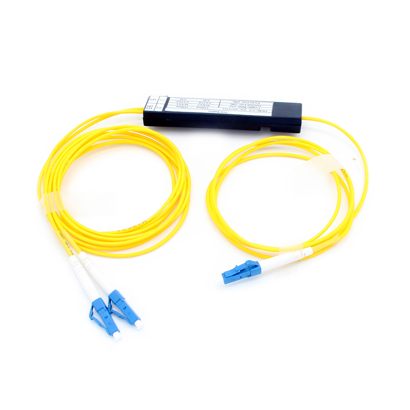
2. PLC Fiber Splitter (Planar Lightwave Circuit)
PLC (Planar Lightwave Circuit) fiber splitter is the most widely used type in modern FTTH and PON networks and represents the mainstream direction of fiber splitting technology today.

Features:
- Technology principle: Planar lightwave circuit technology is used to integrate the optical path with an accurate waveguide chip to efficiently distribute the signal.
- Splitting capacity: Supports large split ratios such as 1×8, 1×16, 1×32, and 1×64 for large-scale deployments.
- Uniformity: Provides consistent optical power distribution across all output ports, ensuring stable signal reception.
- Operating wavelengths: Compatible with 1310nm, 1490nm, and 1550nm transmission windows.
- Stability: Chip-based structure ensures reliable long-term operation in various network environments.
Applications:
- FTTH (Fiber to the Home) networks.
- PON passive optical network systems.
- Fiber distribution in data centers.
- Large residential, commercial, and campus fiber networks.
3. Bare Fiber Splitter
A bare fiber splitter is a fiber splitter without external packaging, where the splitting element is directly connected to exposed optical fibers. This design offers high flexibility for customized applications.

Features:
- Structure: No protective housing, with the splitting chip or fused structure directly connected to fibers.
- Size: Extremely compact, suitable for integration into space-constrained equipment.
- Flexibility: Easy to repackage or integrate with other fiber components.
- Cost advantage: Eliminates external packaging materials, reducing unit cost
Applications:
- Internal integration within optical communication equipment.
- Optical modules and transmission system components.
- Laboratory testing and R&D environments.
- Customized fiber optic communication solutions.
4. Mini Module Fiber Splitter
The mini module fiber splitter adds a compact protective enclosure to a bare fiber or splitter chip, balancing small size with basic protection.

Features:
- Packaging: Metal or high-strength plastic housing provides essential physical protection.
- Compact design: Optimized for installation in limited spaces.
- Protection performance: Reduces the impact of bending, pulling, and external forces on fibers.
- Installation convenience: Modular design allows quick installation and maintenance.
Applications:
- Optical Distribution Frames (ODF).
- Corridor or wall-mounted fiber distribution boxes.
- Small fiber access points.
- Access networks with space and stability requirements.
5. Rack Mount / Cassette Fiber Splitter
Rack mount or cassette fiber splitters integrate fiber splitters into standard racks or modular cassettes, focusing on centralized management and high-density deployment.


Features:
- Installation format: Complies with 19-inch rack or modular cassette standards.
- Management efficiency: Organized fiber routing simplifies maintenance and troubleshooting.
- Scalability: Supports modular expansion for future network growth.
- Engineering compliance: Meets deployment standards for telecom operators and data centers
Applications:
- Telecom operator central offices.
- Data centers and aggregation rooms.
- Metro and access network core nodes.
- Fiber networks require centralized splitting and management.
How to Choose the Right Fiber Splitter?
When selecting a fiber splitter for a practical project, several key factors should be evaluated to ensure network performance and long-term reliability:
- Split ratio: Ratios such as 1×8, 1×16, or 1×32 directly affect network coverage and optical power budget and should be selected based on user density and transmission distance.
- Insertion loss: Insertion loss determines signal attenuation and has a direct impact on transmission quality and reach.
- Port uniformity: Uniform power distribution across output ports ensures consistent signal performance at end devices.
- Packaging type: The appropriate enclosure should be chosen according to the installation environment, such as indoor, outdoor, or central office use.
- Network scale and expansion: Current network size and future growth plans should be considered to select a stable, reliable, and cost-effective fiber splitter
Conclusion
Fiber splitters are different from each other based on the technology used, the capacity of the splitter, the design of the splitter, and the purpose of the splitter. There is no one-size-fits-all solution when it comes to choosing the best type of fiber splitter for the network. Therefore, by choosing the right type of fiber splitter and packaging, network operators are able to balance the performance of the network with the reliability and the cost. As a professional optical communication solution provider, OMC GROUP offers a wide range of fiber splitter products along with expert selection support. For more product information or customized solutions, please feel free to contact us.