Technical Specifications
|
Product name |
UHD 1U 19’ MTP&MPO-LC 144F
Angled Integrated rack mount Patch Panel |
Part no. |
UHD2S3-xxxx |
| Front Adapter Type |
LC UPC Duplex |
Rear Adapter Type |
MTP/MPO (key up-key down) |
| Front Interfaces |
144 |
Rear Interfaces |
12 |
| Insertion Loss |
Standard MPO/MTP≤0.5dB
Super low loss MPO/MTP≤0.35dB, LC≤0.3dB |
Return Loss |
MPO/MTP≥60dB(SM);20dB (MM),
LC≥50dB(SM);35dB(MM) |
| MTP Adapter |
Key up to key down |
Cable Polarity |
Polarity A/B |
| Cassette Type |
1RU 19′ Angled |
Dimensions |
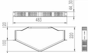
44.3mmx 483mmx 220.2mm |
Drawing
Other Accessories
| 12F MPO-LC 0.9mm fanout 50cm |
End A |
End B |
Optical Performance |
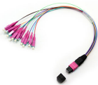 |
1x12F MPO&MTP (Male) with Pin |
12x LC sim-
plex 0.9 con- nectors |
Standard MPO IL<0.5dB
Super low loss MPO IL<0.35dB LC ‘s IL<0.3dB |
| MPO Adapter |
Keyway |
Footprint |
Insertion Loss |
Color |
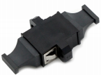 |
Opposed (Up-Down) Aligned (Up-Up) |
MPO/MTP standard |
≤0.2dB |
Black |
| LC DX Reduced flange Adapter |
Keyway |
Footprint |
Insertion |
Color |
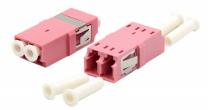 |
Aligned (Up-Up) |
SC Footprint |
≤0.2dB |
SM:BLUE
OM3:AQUA
OM4:MAGENTA
OM5:LIME GREEN |
| LC Reduced flange TF Adapter |
Keyway |
Footprint |
Insertion |
Color |
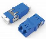 |
Aligned (Up-Up) |
SC Footprint |
≤0.2dB |
SM:BLUE
OM3:AQUA
OM4:MAGENTA
OM5:LIME GREEN |
Design Principles
Integrated Non-Modular Design
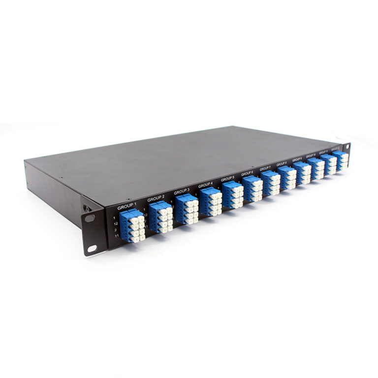
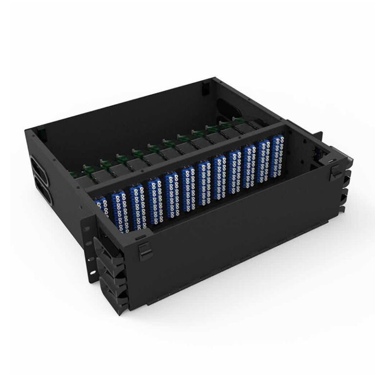
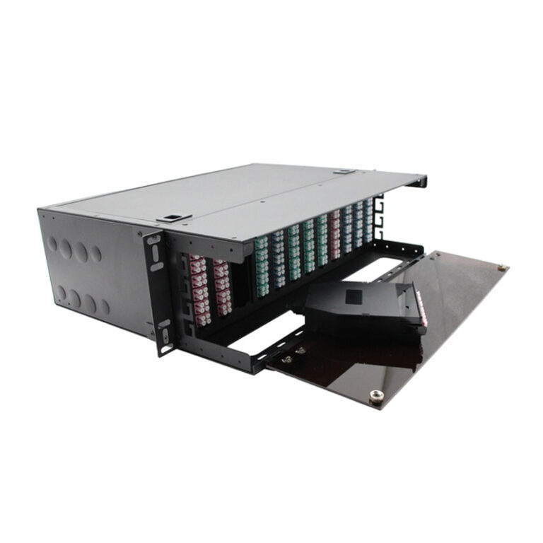
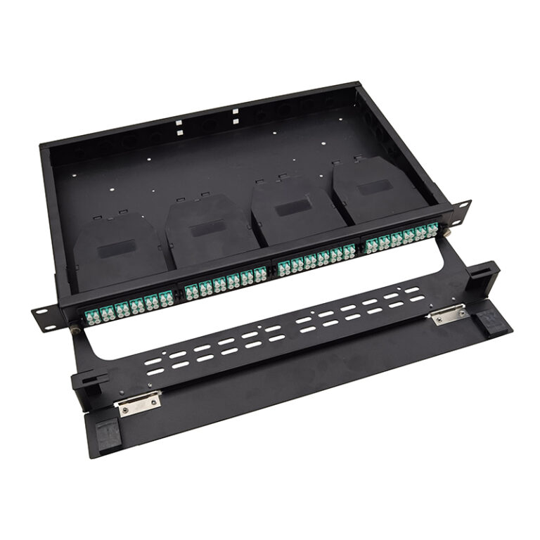
Unlike cassette-based patch panels, this panel is a one-piece integrated breakout unit: the breakout harness is permanently installed at the factory, eliminating modular cassette slots and their associated insertion loss and mechanical tolerance. The result is a compact, robust panel with a clean front face.
Angled LC Mounting
The front LC adapters are mounted on an angled plane. Patch cords exit the adapters at a controlled angle and are guided into the side cable-management channels, keeping the minimum bend radius, reducing
strain on connectors, and improving front-panel readability and access.
Fixed High-Density Breakout
The panel terminates 144 fibers in a single 1U of rack space: 12 MPO-12 trunk interfaces on the rear are bro – ken out into 144 individual LC connections on the front. Each MPO-12 trunk fans out to one 12-LC group,
giving a clean one-to-one mapping. This removes the need for separate LC patch panels and trunk fan-out cassettes, saving rack height and cabling volume.
Factory-Terminated Breakout Harness
The internal interconnection is a pre-terminated, pre-tested 0.9 mm loose-buffered breakout harness with MPO (male) plugs. Because the harness is factory terminated, no splicing or field termination is required dur – ing installation, which improves link quality and shortens deployment time. Each MPO-12 trunk fans out to one 12-LC group, giving a clean one-to-one mapping.
0.9 mm loose–Buffered Fiber Design
0.9 mm loose-buffered fiber provides a compact, robust breakout medium inside the panel. The buffered construction protects the fiber from mechanical stress and simplifies routing while maintaining the required minimum bend radius.
Polarity Management
MPO-based links follow the polarity methods (Type A, Type B and Type C) defined in ANSI/TIA-568.3-D. The fixed breakout harness is manufactured with the selected polarity; trunk cables, harness and patch cords are chosen together to ensure end-to-end polarity consistency.
SPCC Chassis and Standard Mounting
The SPCC chassis offers a light weight, high rigidity and an effective grounding path, while ventilated open – ings allow natural airflow. The panel follows the 19-inch equipment practice (483 mm width, 44.3 mm per rack unit) in accordance with EIA-310-E / IEC 60297-3-100, ensuring drop-in compatibility with standard racks.
International Standards & Compliance
| Standard |
Title / Scope |
| IEC 61754-7 |
Fibre optic connector interfaces — Type MPO connector family (multi-fiber push-on). |
| TIA-604-5 (FOCIS 5) |
Fiber optic connector intermateability standard — Type MPO. |
| ISO/IEC 11801-1 |
Information technology — Generic cabling for customer premises. |
| ANSI/TIA-568.3-D |
Optical fiber cabling components standard (including MPO polarity Methods A/B/C). |
| Telcordia GR-1209-CORE |
Generic requirements for passive optical components. |
| Telcordia GR-1221-CORE |
Generic reliability assurance requirements for passive optical components. |
| Telcordia GR-1435 |
Generic requirements for multi-fiber optical connectors. |
| IEC 61300-3-4 |
Basic test and measurement procedures — Attenuation (insertion loss measurement). |
| IEC 60825-1 |
Safety of laser products — Part 1: Equipment classification and requirements. |
| EIA-310-E / IEC 60297-3-100 |
19-inch rack equipment practice: 482.5 mm width, 44.45 mm per rack unit. |
| RoHS 2011/65/EU |
Restriction of hazardous substances. |
Application
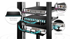
Data centers — MDA / HDA / EDA zones: 40G, 100G or 400G MPO backbone links terminated on the rear, fanned out to duplex LC server and switch access ports.
Enterprise and campus LAN — backbone consolidation and high-density patching in equipment rooms and telecommunications rooms.
Telecom central offices and FTTx — high-density single-mode (OS1/OS2) fiber distribution and ODF-style termination.
Cloud and colocation facilities — space-constrained patching where every rack unit of height is at a premi – um.
Storage networks (SAN) and high-performance computing — deterministic, high-channel-count fiber management.
Installation
Mount the panel on 19-inch rack rails using the slotted mounting ears; tighten all rack screws to prevent movement.
Connect the chassis grounding stud to the rack earth before cabling.
Plug MPO trunk cables into the rear MPO-12 adapters; the internal breakout harness is already factory – terminated, so no splicing is required.
Route front patch cords into the angled cable-management channels, respecting the minimum bend radius of the cables.
Label each group (G1–G12) and port according to the local labeling plan.
Maintenance
Clean connector ferrules before every mating; always fit dust caps on unused adapters and connectors.
Do not look directly into a fiber end-face or adapter while a light source is connected — laser safety per IEC 60825-1.
Keep fibers within their bend radius at all times; avoid sharp folds and tensile loads on patch cords and trunk cables.
Check insertion loss after re-mating; repeated contamination is the most common cause of excess loss in high-density patching.
Order Index
Full loaded MPO/MTP–LC 96F Patch panel
| Patch panel |
MPO adapter |
LC adapter |
MPO/MTP Quality level |
Fiber mode |
| UHD2S –3 |
0-unloaded |
0-unloaded |
0-unloaded |
0– unloaded |
|
1-Opposed (Up- Down) |
1-Lc Standard DX no flange |
1-Standard loss Senko MPO Male |
1– G657A1 |
|
2-Aligned (Up- Up) |
2-Lc Standard DX no flange TF Type |
2-Super low loss Senko MPO Male |
2-G657A2/B2 |
|
|
|
3-Standard loss MTP Male |
3-G657B3 |
|
|
|
4-Super low loss Elite MTP Male |
4-BIF OM1 |
|
|
|
5-Standard loss OMC MPO Male |
5-BIF OM2 |
|
|
|
6-Super low loss OMC MPO Male |
6-BIF OM3
7-BIF OM4
8-BIF OM5 |
For Example:UHD2S-3-1-1-1-1