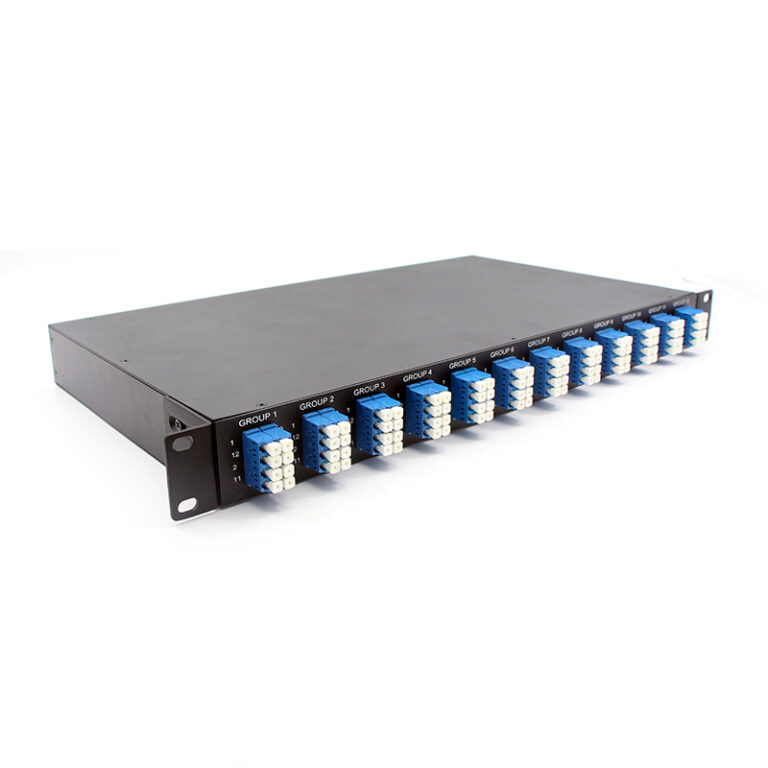
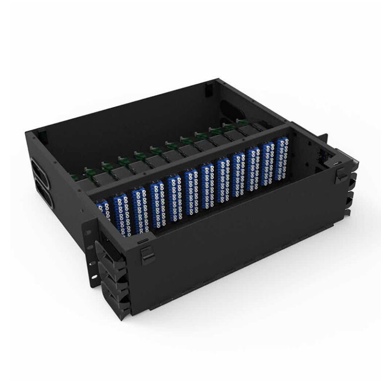
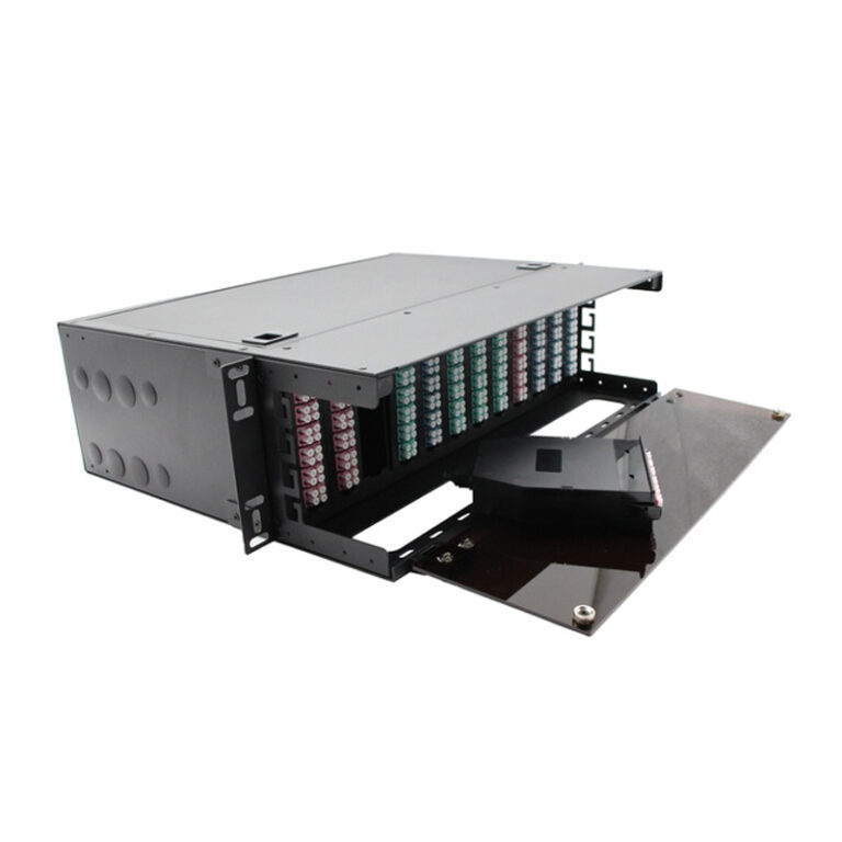
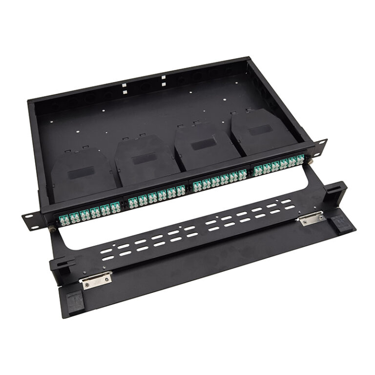
Technical Specifications
|
Product name |
FHD 1U 19’ MTP&MPO-LC 96F
Integrated rack mount Patch Panel |
Part no. |
FHD3F-xx |
| Front Interfaces |
24xLC quad |
Rear Interfaces |
12x MTP/MPO-8 Male (pinned) Key up-Key down |
|
Insertion Loss |
Standard MPO/MTP≤0.5dB
Super low loss MPO/MTP≤0.35dB, LC≤0.3dB |
Return Loss |
MPO/MTP≥60dB(SM);20dB(MM), LC≥50dB(SM);35dB(MM) |
|
MPO&MTP adapter |
Key up to key down |
Dimensions |
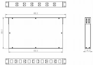
44.2mmx 482.5mmx 250.4mm |
| Chassis Material |
Aluminum alloy |
Total Fiber Count |
96Fiber Max |
Drawing
Other Accessories
| 8F MPO-LC 0.9mm fanout 50cm |
End A |
End B |
Optical Performance |
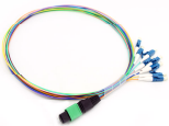 |
1x8F MPO&MTP (Male) with Pin |
8x LC simplex
0.9 connectors |
Standard MPO IL<0.5dB
Super low loss MPO IL<0.35dB LC ‘s IL<0.3dB |
| MPO Adapter |
Keyway |
Footprint |
Insertion Loss |
Color |
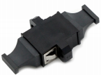 |
Opposed (Up-Down) Aligned (Up-Up) |
MPO/MTP standard |
≤0.2dB |
Black |
| LC Quad Reduced flange Adapter |
Keyway |
Footprint |
Insertion |
Color |
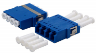 |
Aligned (Up-Up) |
SC Footprint |
≤0.2dB |
SM:BLUE
OM3:AQUA
OM4:MAGENTA
OM5:LIME GREEN |
Design Principles
Fixed High-Density Breakout
The panel terminates 96 fibers in a single 1U of rack space: 8 MPO-12 trunk interfaces on the rear are broken out into 96 individual LC connections on the front. This removes the need for separate LC patch panels and trunk fan-out cassettes, saving rack height and cabling volume.
Factory-Terminated Breakout Harness
The internal interconnection is a pre-terminated, pre-tested 0.9 mm tight-buffered breakout harness with
MPO (male) plugs. Because the harness is factory terminated, no splicing or field termination is required dur – ing installation, which improves link quality and shortens deployment time.
0.9 mm Loose–Buffered Fiber Design
0.9 mm Loose-buffered fiber provides a compact, robust breakout medium inside the panel. The buffered construction protects the fiber from mechanical stress and simplifies routing while maintaining the required minimum bend radius.
Polarity Management
MPO-based links follow the polarity methods (Type A, Type B and Type C) defined in ANSI/TIA-568.3-D. The fixed breakout harness is manufactured with the selected polarity; trunk cables, harness and patch cords are chosen together to ensure end-to-end polarity consistency.
Aluminum Chassis and Standard Mounting
The aluminum alloy chassis offers a light weight, high rigidity and an effective grounding path, while ventilat – ed openings allow natural airflow. The panel follows the 19-inch equipment practice (482.6 mm width, 44.45 mm per rack unit) in accordance with EIA-310-E / IEC 60297-3-100, ensuring drop-in compatibility with
standard racks.
Fiber Protection and Cable Management
Rear trunk-cable retention and front patch-cord guides keep cables within their bend radius and provide strain relief, protecting the internal breakout harness against micro-bending loss and accidental damage.
International Standards & Compliance
| Standard |
Title / Scope |
| IEC 61754-7 |
Fibre optic connector interfaces — Type MPO connector family (multi-fiber push-on). |
| TIA-604-5 (FOCIS 5) |
Fiber optic connector intermateability standard — Type MPO. |
| ISO/IEC 11801-1 |
Information technology — Generic cabling for customer premises. |
| ANSI/TIA-568.3-D |
Optical fiber cabling components standard (including MPO polarity Methods A/B/C). |
| Telcordia GR-1209-CORE |
Generic requirements for passive optical components. |
| Telcordia GR-1221-CORE |
Generic reliability assurance requirements for passive optical components. |
| Telcordia GR-1435 |
Generic requirements for multi-fiber optical connectors. |
| IEC 61300-3-4 |
Basic test and measurement procedures — Attenuation (insertion loss measurement). |
| IEC 60825-1 |
Safety of laser products — Part 1: Equipment classification and requirements. |
| EIA-310-E / IEC 60297-3-100 |
19-inch rack equipment practice: 482.5 mm width, 44.45 mm per rack unit. |
| RoHS 2011/65/EU |
Restriction of hazardous substances. |
Application
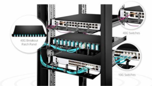
Data centers — MDA / HDA / EDA zones: 40G, 100G or 400G MPO backbone links terminated on the rear, fanned out to duplex LC server and switch access ports.
Enterprise and campus LAN — backbone consolidation and high-density patching in equipment rooms and telecommunications rooms.
Telecom central offices and FTTx — high-density single-mode (OS1/OS2) fiber distribution and ODF-style termination.
Cloud and colocation facilities — space-constrained patching where every rack unit of height is at a premi – um.
Storage networks (SAN) and high-performance computing — deterministic, high-channel-count fiber management.
Installation
Mount the panel on 19-inch rack rails using the slotted mounting ears; tighten all rack screws to prevent movement.
Connect the chassis grounding stud to the rack earth before cabling.
Plug MPO trunk cables into the rear MPO-12 adapters; the internal breakout harness is already factory – terminated, so no splicing is required.
Patch the front LC ports with LC patch cords, respecting the minimum bend radius of the cables.
Label each group and port according to the local labeling plan.
Maintenance
Clean connector ferrules before every mating; always fit dust caps on unused adapters and connectors.
Do not look directly into a fiber end-face or adapter while a light source is connected — laser safety per IEC 60825-1.
Keep fibers within their bend radius at all times; avoid sharp folds and tensile loads on patch cords and trunk cables.
Check insertion loss after re-mating; repeated contamination is the most common cause of excess loss in high-density patching.
Order Index
Full loaded MPO/MTP–LC 96F Patch panel
| Patch panel |
MPO adapter |
LC adapter |
|
MPO/MTP Quality level |
Fiber mode |
| FHD3F |
0-unloaded |
0-unloaded |
|
0-unloaded |
0– unloaded |
| 1-Opposed (Up- Down) |
1-Lc Standard Quad no flange |
|
1-Standard loss Senko MPO Male |
1– G657A1 |
| 2-Aligned (Up- Up) |
|
|
2-Super low loss Senko MPO Male |
2-G657A2/B2 |
|
|
3-Standard loss MTP Male- |
3-G657B3 |
|
|
4-Super low loss Elite MTP Male |
4-BIF OM1 |
|
|
5-Standard loss OMC MPO Male |
5-BIF OM2 |
|
|
6-Super low loss OMC MPO Male |
6-BIF OM3 |
|
|
|
7-BIF OM4 |
|
|
|
8-BIF OM5 |
For Example:FHD3F-1-1-1-1