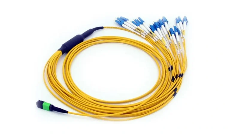
Choosing the wrong type of fiber optic cable during the installation can lead to signal attenuation, limited transmission range, and additional expenses associated with replacing the equipment later. Despite the fact that OS1 and OS2 cables look alike (they usually have the same yellow outer jacket), their structure, attenuation coefficient, and transmission capabilities vary significantly. This information will help you select the correct Single Mode Patch Cord.
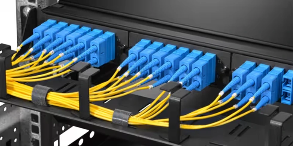
1. What Are OS1 and OS2 Single Mode Patch Cords?
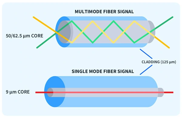
Both OS1 and OS2 fiber optics belong to the Single Mode Patch Cord category. Unlike multimode cables with 50-micron or 62.5-micron cores, a standard single-mode patch cord consists of a narrow 9-micron glass core (9/125μm) which is surrounded by 125-micron cladding. Because the core is thin, light beams do not scatter while traveling along the cable but travel in one straight line. Thus, there is no modal dispersion, and data transmission occurs over long distances at increased bandwidth.
The distinction between OS1 and OS2 is connected to international standards and glass manufacturing techniques. The first type of cable appeared according to the ISO/IEC 11801 standard and is compliant with ITU-T G. 652 and G.652.B specifications. It was designed for indoor enterprise cabling needs. OS2 appeared later and was adopted according to ISO/IEC 24702 and ITU-T G.652.D (along with bend-insensitive G.657.A1 and G.657.A2). OS2 glass manufacturers use low-water-peak technology, which excludes hydroxide ions and provides free-spectrum signal transmission at 1383nm.
2. Main Differences Between OS1 and OS2 Single Mode Patch Cord
While you can connect both Single Mode Patch Cord types to the same transceivers and patch panels, their optical and mechanical properties differ in three crucial ways.
2.1 Cable Structure and Buffering Type
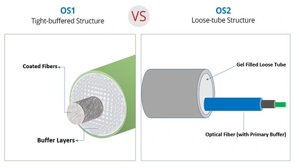
Most manufacturers produce OS1 Single Mode Patch Cords using a tight-buffered cable design. This means that there is a thick layer of polymer covering the cable cladding. Extra protection increases cable crush resistance and allows easy stripping, terminating, and routing the cable through tight indoor conduits.
In the case of OS2 Single Mode Patch Cord, loose tube design is used for outdoor applications, and modern bend-insensitive tight buffered design is used for indoor high-density patch panels. In a loose tube cable, glass fiber is placed inside a semi-rigid protective tube filled with water-blocking gel or dry absorbent yarns. Such buffering provides isolation of sensitive glass fiber from thermal expansion and contraction as well as from physical pull-out tension, which causes microbend losses.
2.2 Signal Attenuation and Maximum Range
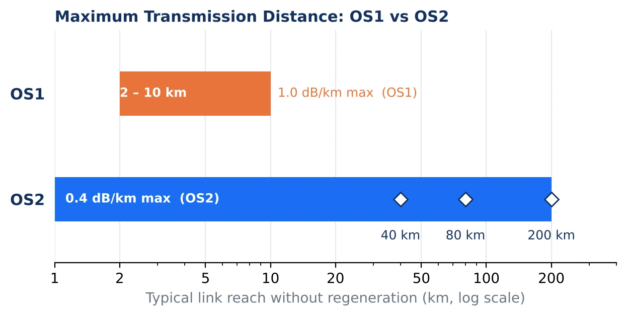
Attenuation is the measurement of the loss of power over distance and defines the maximum possible distance of cable connection. OS1 Single Mode Patch Cord has maximum signal attenuation of 1.0 dB/km at 1310nm and 1550nm wavelengths. Thus, using an OS1 patch cord, you can connect two devices within a distance of 2 km to 10 km.
Because OS2 fiber optic cables use pure silica glass, the maximum attenuation is lowered to 0.4 dB/km in 1310nm and 1550nm wavelength windows, with premium products having 0.25dB/km attenuation. Lowering signal attenuation by half allows connecting devices using OS2 patch cords over long distances up to 40km, 80km and even 200km without any active signal regeneration.
2.3 Wavelengths of Operation and WDM Support
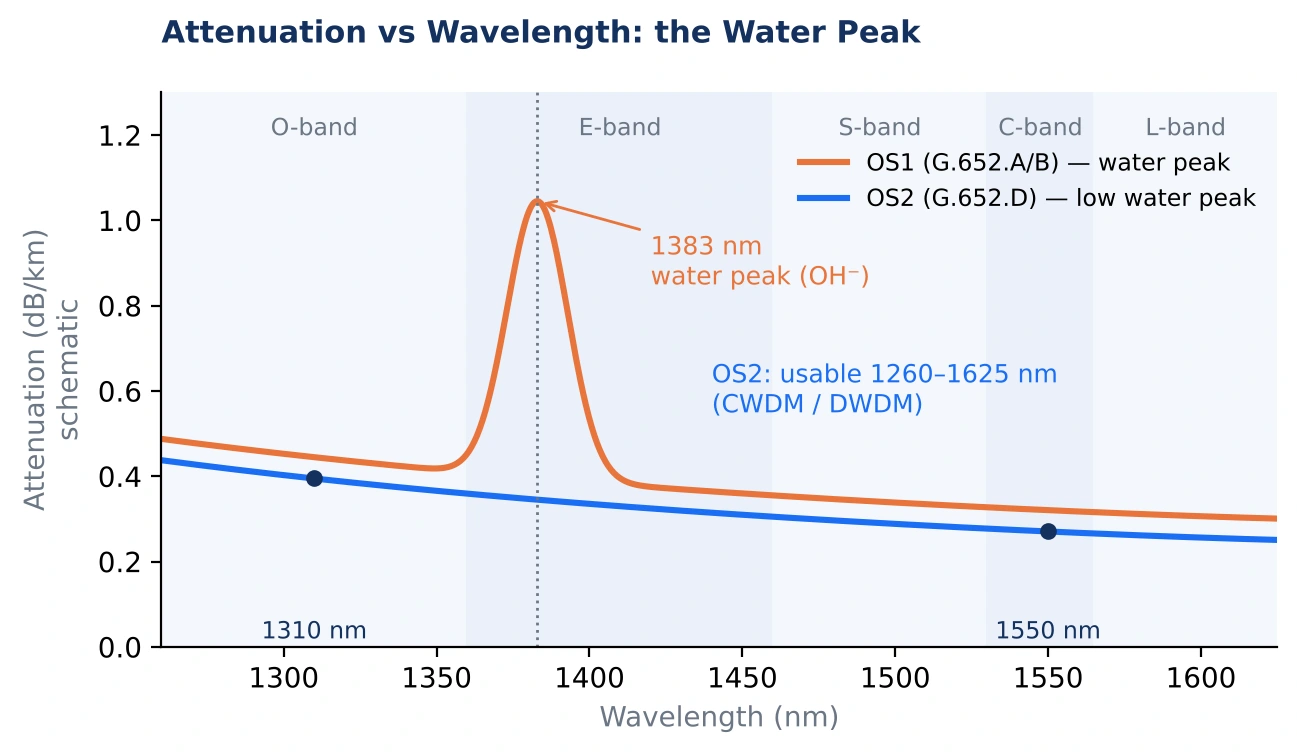
The standard operating wavelength range of OS1 fiber optics is limited by 1310nm and 1550nm. Water molecules present in the glass cause high attenuation at 1383nm wavelength, leaving the middle part of the optical spectrum unused.
The use of low-water-peak technology in OS2 makes it possible to use the whole range of 1260nm to 1625nm for signal transmission. This large window makes it possible to operate both Coarse Wavelength Division Multiplexing and Dense Wavelength Division Multiplexing. Sending multiple wavelengths of light through one OS2 single-mode patch cord is the way to increase network capacity without laying additional fiber trunks.
Technical Specifications Comparison
| Specification | OS1 Single Mode Patch Cord | OS2 Single Mode Patch Cord |
| Governing Standards | ISO/IEC 11801 (ITU-T G.652.A/B) | ISO/IEC 24702 (ITU-T G.652.D / G.657) |
| Typical Structure | Tight-buffered | Loose-tube or bend-insensitive tight-buffered |
| Max Attenuation | 1.0 dB/km at 1310nm / 1550nm | 0.4 dB/km at 1310nm / 1550nm |
| Operating Wavelength | 1310nm and 1550nm | 1260nm to 1625nm (Low Water Peak) |
| Maximum Distance | 2 km to 10 km | Up to 200 km |
| Common Data Rates | 1G / 10G Ethernet | 10G / 40G / 100G / 400G Ethernet |
| Primary Environments | Indoor office spaces, campus access | Data centers, telecom backbones, FTTH/outdoor |
3. How To Choose The Right Single Mode Patch Cord?
Consider distance/physical routing, future needs, and the type of connector polish you need before ordering your Single Mode Patch Cord.
When your fiber optic cables will never leave the boundaries of one building (wiring closet to wiring closet in a series of buildings over distances shorter than 2 kilometers), an OS1 single-mode patch cord will work for 1G and 10G Ethernet connections. But if the cabling route passes through underground conduits, aerial utility poles, or an open campus environment, OS2 will be needed to withstand different temperatures and longer distances.
In all aspects of the optical networking industry, the use of OS1 has been almost entirely supplanted by OS2. As an OS2 Single Mode Patch Cord is backward compatible with existing OS1 equipment and transceivers, choosing OS2 saves you money. You can rest assured that your optical cabling infrastructure will have enough room for upgrades to 40G, 100G, and 400G transceivers while being priced almost equally to OS1 today.
Aside from the glass standard itself, make sure you know the end-face shape of connectors that is expected by your equipment. The Ultra Physical Contact (UPC) connectors with blue boots allow achieving return loss of -50dB, which is fine for data center switches and enterprise servers. The Angled Physical Contact (APC) connectors with green boots have an 8-degree angle in their end-face, achieving -60dB or more return loss. The special angle prevents reflected light from bouncing back to the source laser and is mandatory for FTTH PON and analog RF video applications.
Conclusion
Although OS1 did a good job serving early indoor enterprise cabling runs, OS2 has clearly proven to be the industry standard. With attenuation not exceeding 0.4 dB/km, maximum reach of 200 km, and full compatibility with CWDM and DWDM technologies, an OS2 single-mode patch cord gives you top performance and future compatibility in your data centers, carrier telecommunication networks, and FTTH networks.
Proper selection of the optical cable standard based on your power budget guarantees your smooth operation without unexpected outages or costly rework. If you have any questions regarding the selection of a proper Single Mode Patch Cord, calculation of link loss, and fiber optic cable cabling plan, contact us – our technical team at OMC is always ready to assist you.