In modern communication technology, fiber optic networks have become the main force of information transmission with their high speed, high bandwidth, and anti-interference. As one of the key components in fiber optic networks, cs plays a vital role. This article will take you to understand the working principle, application scenarios, and how it affects our digital life of fiber splitters
The working principle of fiber splitters
Fiber splitter is a passive fiber optic device also known as a fiber splitter or fiber coupler. The main function of the splitter is to distribute optical signals from one single fiber to multiple optical fibers or to merge optical signals from multiple optical fibers into one fiber. This process can be called “dividing” and “combining” optical signals.
What are the types of fiber splitters?
By port configuration
Fiber splitters can be 1×2, 1×4, 1×8, 1×16, 1×32, and 1×64 according to different port configurations based on clients requirements. [Note: On the semiconductor plate, “Y”-shaped waveguide couplers are engraved using photolithography technology. Connecting these “Y” waveguides together forms a step-by-step splitting, which can achieve splitting ratios such as 1×2, 1×4, 1×8, 1×16, 1×32, and 1×64. ]
According to the working wavelength
According to the working wavelength, fiber splitters can be divided into single-window fiber splitters and double-window fiber splitters. Single-window fiber splitters have one working wavelength, while double-window has two working wavelengths.
According to the manufacturing process
For fiber splitters, there will be different manufacturing processes, so fiber splitters are divided into planar waveguide (PLC) fiber splitters and fused taper (FBT) fiber splitters based on it.
Planar waveguide (PLC) fiber splitter
FBT splitter uses traditional fused taper technology to melt two (or more) optical fibers at high temperatures, monitor the change of splitting ratio in real-time, and end the melting and stretching after the splitting ratio reaches the requirement. Due to the simple process and equipment, its cost is lower.
PLC fiber splitter are used to achieve branch distribution functions from optical waveguides on dielectric or semiconductor substrates from photolithography technology. There is a wide variety of splitting ratios that can be provided, such as 1:2, 1:4, 1:8, 1:16, etc.
The splitting methods of these two fiber splitters are similar, they both achieve different branching amounts by changing the mutual coupling (coupling degree, coupling length) of the evanescent field between optical fibers and changing the diameter of the optical fiber.
According to the packaging type
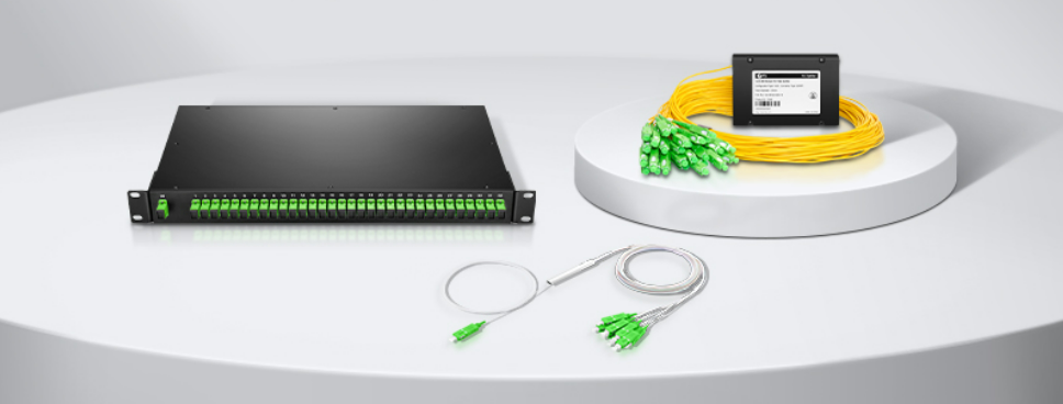
At present, there are five common packaging types for fiber splitters: bare fiber type, micro type, ABS box type, LGX box type and rack type.
Bare fiber type fiber splitter
As we all know, a bare fiber type fiber splitter has no connector, so the carrier box or equipment needs to have a perfect protection design. Due to its compact structure and small size, it can be easily installed in the distribution box, fully improving the space utilization rate, while reducing the installation cost, suitable for FTTH, PON, LAN, CATV, and other applications.
Mini fiber splitter
Although the appearance of the mini fiber splitter is similar to that of the bare fiber type fiber splitter, it adopts a more compact stainless steel tube packaging design to provide stronger fiber protection. In addition, the mini fiber splitter does not require fiber fusion during installation and is generally used in a distribution box or network cabinet.
ABS box-type fiber splitter
The ABS box-type fiber splitter is equipped with an ABS plastic shell to protect internal optical devices and optical cables from damage. In addition, it has a compact structure, can adapt to different application environments, and can be flexibly installed in various distribution cabinets or chassis.
LGX module fiber splitter
The LGX splitter has a sturdy metal casing or plastic cover that can be used alone or easily deployed in a standard fiber distribution frame or chassis.
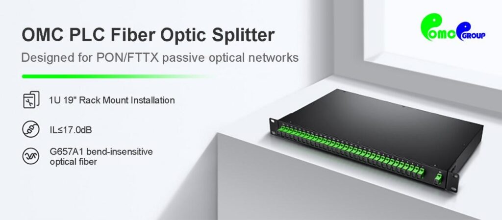
Rack-mounted fiber splitter
the sizes we often use for rack-mounted fiber splitters are 1U and 2U, but 1U rack-mounted fiber splitters are more commonly used. OMC 1U 19″ rack-mounted fiber splitter can be installed in a standard 19-inch network cabinet or rack. It is easy to install and maintain and is widely used in EPON, GPON, FTT, X, and FTTH networks providing ideal solutions for high-density wiring environments.
What factors should be considered when selecting a fiber splitter?
Faced with the above many types of fiber splitters, how should we choose? Generally speaking, the selection of fiber splitters can be considered in combination with the following parameters:
- Insertion loss: The insertion loss of a fiber splitter refers to the dB loss of a certain output light relative to the input light. Generally, if the insertion loss is smaller, the better the performance of the fiber splitter.
- Return loss: Return loss, also known as reflection loss, refers to the power loss of the optical signal returned or reflected by the discontinuity in the optical fiber or transmission line. Generally, it will be better if the return loss greater
- Splitting ratio: The splitting ratio refers to the output power of each output port of the fiber splitter. In network applications, it will be based on the amount of optical power required by the actual system optical node to determine the appropriate splitting ratio (except for the average distribution).
As the cornerstone of the optical fiber communication network, the development and application of fiber splitter technology is of great significance to improving network speed, reducing costs, and improving reliability. With the rise of new technologies such as 5G and the Internet of Things, the role of fiber splitters will become more prominent, and they will continue to play an indispensable role in the digital world.